Guarantee: 3 many years
Applicable Industries: Hotels, Garment Stores, Developing Materials Stores, Production Plant, Machinery Fix Stores, Meals & Beverage Manufacturing facility, Farms, Restaurant, Retail, Food Shop, Printing Stores, Development works , Power & Mining, Foodstuff & Beverage Stores, Advertising and marketing Company
Tailored help: OEM, ODM
Kind: Spherical BELT
Content: ALLOY
Application: GT2 Sprockets timing pulley GT2 belt Pulley Synchronous
Procedure: Precision manufactured and static balanced
Shape: Scaled-down, narrower sprockets preserve shaft area, keep nearer to bearing
Packing: Bubble Bag+Box
Belt Width: 4-50mm
Edge: Complete split in bushing enables straightforward set up and removing
Timing Pulley Sort: T10 Timing Belt Pulley
High quality Handle: Inspection Department
Tolerance: .02mm
Delivery Time: 15-35 Days
Packaging Information: 1. Business packing: Bubble luggage, carton, wooden box for risk-free deal 2. As the customers’ specifications
Synchronous Electricity Transmission Pulleys Timing Belts and Pulleys for Synchronous Travel Components
1) Guarantee: our timing pulley’s good quality is very very good and with ensurance inside 1 calendar year, when you obtain the products and uncover high quality difficulties, we promise you could return it again and totally free servicing.
two) Drawings: make sure you ship you timing pulleys’ drawings to us to get the greatest quotation If you have no drawings, then we could work out CAD drawings and the very best quotation to you ASAP.three) Sample: we take 1 piece sample’s get, we could do samples till you happen to be content.4) Confidentiality agreetment: Strictly adherence to client confidentiality agreetment for timing pulleys.
| Product Identify | Timing Belt Pulley | |
| Teeth profile | Trapezoidal toothed | MXL, XXL, XL, L, H, XH, XXH |
| T-toothed | T2.5, T5, T10, T20 | |
| Arc toothed | HTD3M, HTD5M, HTD8M, HTD14M, HTD20M, Gt2, Gt3, Gt5 | |
| S-toothed | S2M, S3M, S4.5M, S5M, S8M, S14M | |
| Parabolic-toothed | P2M, P3M, P5M, P8M, P14M | |
| Y-toothed | G2M, G3M, G5M, Y8M | |
| Teeth Amount | 10-one hundred fifty teeth or tailored | |
| Inner Bore | 2-200mm H7 precision or custom-made | |
| Belt width | 4mm, 6mm, 9mm, 10mm, 12mm, 15mm, 20mm, 25mm, 30mm, 40mm, 50mm, 1/4”, 5/16”, 3/8”, 1/2”, 3/4”, 1”, 1.5”, 2”or custom-made | |
| Equipment | We can give the support of assembling setscrews, bearings, shafts or taper bush | |
| Floor treatment method | Anodize,Black Oxide,Phosphate and Galvanization | |
| Drawing Format | Timing belt pulley cad drawing,timing belt pulley UG drawing,Timing belt Pulley Soliwork drawing,Timing Pulley PDF drawing | |
What is timing pulley?
Timing pulleys are specialised pulleys that have possibly enamel or pockets close to the exterior diameter of the pulley human body. Timing enamel interact holes in the steel belt, whilst timing pockets have interaction generate lugs on a belt’s interior circumference. These enamel or pockets are used only for timing, not for electrical power transmission.
How timing pulleys function?
The synchronous wheel transmission is composed of an limitless belt with equivalent-spaced tooth on the interior peripheral area and a pulley with corresponding teeth. For the duration of operation, the toothed enamel mesh with the tooth grooves of the pulley to transmit motion and electricity, which is built-in with the belt. A new kind of belt generate with the benefits of transmission, chain travel and gear transmission.
What is gt2 timing pulley?
2mm pitch GT2 Pulley. The GT2 or 2GT Tooth Profile timing pulley prevails in the 3d printing hobby cause the Round tooth profile delivers large precision of non-backlash, ended up known as present-day Reprap Pulley.
What is a timing pulley flange?
Timing pulley flanges are used to sustain belt contact with a timing pulley in electricity transmission applications.Timing pulley flanges are created to fit timing pulleys of the same pitch and size. The dimensions of a pitch, which includes the mating flange, are specified by the variety of grooves.
What are synchronous belts employed for?
The trapezoidal tooth profile 1st utilized on synchronous belts is identified as normal. Belts with this configuration are commonly employed in equipment equipment, textile machinery, residence appliances, organization products, and as camshaft drives in engines.
Notice:Remember to verify you need enamel profile, teeth quantity, belt width, bore diameter, quantity and sort (remember to refer below drawings) to get our the most full CAD drawings and the best quotation.
Relevant Merchandise
Calculate the ideal mechanical advantage of pulleys
The basic equations for pulleys can be found in this article. It will also cover the different types of pulleys, the ideal mechanical advantages of pulleys, and some common uses of pulley systems. Read on to learn more! After all, a pulley is a simple mechanical device that changes the direction of a force. Learn more about pulleys and their common uses in engineering.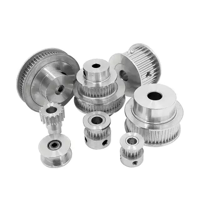
pulley basic equation
Pulleys work the same way as gravity, so they should withstand similar forces. Newton’s laws of motion can be used to calculate the forces in a pulley system. The second law of motion applies to forces and accelerations. Similar to this is Newton’s third law, which states that the directions of forces are equal and opposite. The fourth law dictates the direction of force. The Fifth Law states that tension is in equilibrium with gravity.
A pulley is a simple mechanism that transmits force by changing direction. They are generally considered to have negligible mass and friction, but this is only an approximation. Pulleys have different uses, from sailboats to farms and large construction cranes. In fact, they are the most versatile mechanisms in any system. Some of their most common applications and equations are listed below.
For example, consider two masses m. Those of mass m will be connected by pulleys. The static friction coefficient of the left stop is ms1, and the static friction coefficient of the right stop is ms2. A no-slip equation will contain multiple inequalities. If the two blocks are considered to be connected by a pulley, the coefficient of kinetic friction is mk. In other words, the weight of each block carries the same mass, but in the opposite direction.
Types of pulleys
A pulley is a device used to pull and push objects. Pulley systems are ropes, cables, belts or chains. The “drive pulley” is attached to the shaft and moves the driven pulley. They are available in a variety of sizes, and the larger they are, the higher the speed of power transmission. Alternatively, use small pulleys for smaller applications.
Two-wheel pulleys have two mechanical advantages. The greater the mechanical advantage, the less force is required to move the object. More wheels lift more weight, but smaller pulleys require less force. In a two-wheel pulley system, the rope is wound around two axles and a fixed surface. As you pull on the rope, the shafts above slowly come together.
Compound pulleys have two or more rope segments that are pulled up on the load. The mechanical advantage of compound pulleys depends on the number of rope segments and how they are arranged. This type of pulley can increase the force by changing the direction of the rope segment. There are two main types of pulleys. Composite pulleys are most commonly used in construction. The ideal mechanical advantage of pulleys is 2 or more.
Construction pulleys are a basic type. They are usually attached to wheel rails and can be lifted to great heights. Combinations of axes are also common. Construction pulleys can be raised to great heights to access materials or equipment. When used in construction, these pulleys are usually made of heavy materials such as wood or metal. They are secured with ropes or chains.
The ideal mechanical advantage of pulleys
The pulley system is a highly complex system with high mechanical advantages. Use a single pulley system to reduce the force required to lift an object by cutting it in half. The mechanical advantage increases as you add more pulleys, such as six or seven. To calculate the mechanical advantage of a pulley system, you need to count the number of rope segments between the pulleys. If the free end of the rope is facing down, don’t count it. If it’s facing up, count. Once you have your number, add it up.
The required mechanical advantage of a pulley is the number of rope segments it has to pull the load. The more rope segments, the lower the force. Therefore, the more rope segments the pulley has, the lower the force. If the rope segments are four, then the ideal mechanical advantage is four. In this case, the composite pulley quadrupled the load force.
The ideal mechanical advantage of a pulley system is the sum of the mechanical force and the force required to lift the load at its output. Typically, a single pulley system uses two ropes, and the mechanical force required to lift the load is multiplied by the two ropes. For a multi-pulley system, the number of ropes will vary, but the total energy requirement will remain the same. The friction between the rope and pulley increases the force and energy required to lift the load, so the mechanical advantage diminishes over time.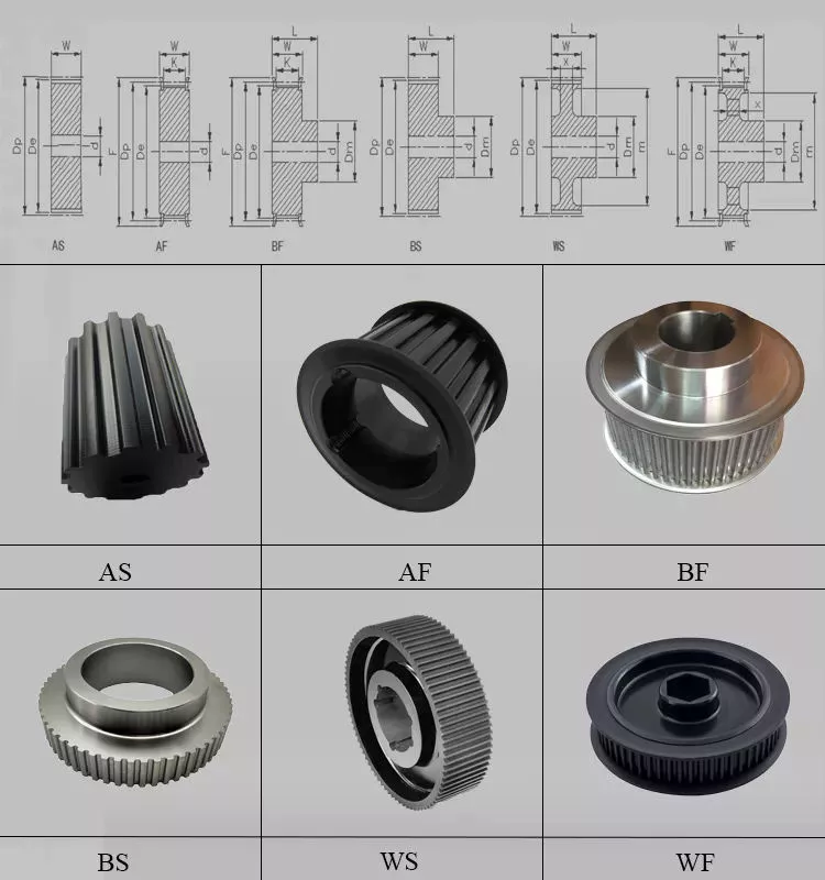
Common uses of pulley systems
A pulley system is a simple mechanical device typically used to lift heavy objects. It consists of a rotating wheel attached to a fixed shaft and a rope attached to it. When the wheel moves, the force applied by the operator is multiplied by the speed of the pulley, and the force is multiplied by the weight of the object being lifted. Common uses for pulley systems include pulling, lifting, and moving heavy objects.
The oil and petroleum industries use pulley systems in a variety of applications. Most commonly, pulleys are used in drilling operations and they are installed on top of the rig to guide the cable. The cable itself is attached to two pulleys suspended in the derrick, where they provide mechanical energy to the cable. Using a pulley system in this application provides the force needed to move the cable safely and smoothly.
The main advantage of the pulley system is that it minimizes the force required to lift an object. The force used to lift the object is multiplied by the desired mechanical advantage. The more rope segments, the lower the force required. On the other hand, a compound pulley system can have many segments. Therefore, a compound pulley system can increase the force a worker can exert on an object.
Safety Precautions to Take When Working on Pulley Systems
There are many safety precautions that should be observed when working on a pulley system. The first is to wear proper protective gear. This includes hard hats that protect you from falling objects. Also, gloves may be required. You should limit the amount of movement in the penalty area, and you should also keep the area free of unnecessary people and objects. Also, remember to wear a hard hat when working on the pulley system.
Another important safety precaution when working on a pulley system is to check the Safe Working Load (SWL) of the pulley before attaching anything. This will help you understand the maximum weight the pulley can hold. Also, consider the angle and height of the pulley system. Always use safety anchors and always remember to wear a hat when working on a pulley system.
Safe use of chain hoists requires training and experience. It is important to read the manufacturer’s manual and follow all safety precautions. If you’re not sure, you can actually inspect the hoist and look for signs of damage or tampering. Look for certifications for sprocket sets and other lifting accessories. Look for the Safe Working Load (SWL) marking on the chain hoist.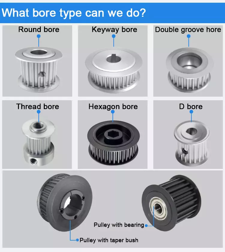
Example of a pulley system
Pulley systems are often used to lift items. It allows you to reduce the effort to lift and move the load by applying force in one direction. Pulley systems can be built and modeled to fit any type of project. This resource focuses on pulley systems and is designed to support the new GCSEs in Engineering, Design and Technology. There are also many examples of pulley systems suitable for various applications.
In the study, participants who read easy text took longer to manipulate the pulley system than those who read challenging text. In general, this suggests that participants with prior scientific experience used their cognitive abilities more effectively. Additionally, students who read simple texts spent less time planning the pulley system and more time on other tasks. However, the study did show that the time required to plan the pulley system was similar between the two groups.
In everyday life, pulley systems are used to lift various objects. Flagpoles are one of many pulley systems used to raise and lower flagpoles. They can also be used to raise and lower garage doors. Likewise, rock climbers use pulleys to help them ascend and descend. The pulley system can also be used to extend the ladder.


editor by czh


